Review Of The RCI 2950DX
FROM: https://cbworldinformer.com/index.htm
About CB World Informer
CB World
Informer�
was first published in July of 1996. The
first issue for August of 1996 included a review of the
ChipSwitch. This 6 page review covered the complete
operation including the user manual. An explanation of the
functions of the radio after installation. Also a list of
equipment needed to perform the installation with a
supplier, supplier part numbers and prices. In addition to
this article there were others including
How To Make The Best Solder Joints,
Slick Tricks On Microphone Wiring,
Proper Base Station And Mobile Grounding and
Advertising Claims...Smoke And Mirrors?.
Review Of The RCI 2950DX
The RCI 2950 has been around for many
years. The first radio of this type from Ranger
Communications was the RCI 2900. The 2900 radio was a CPU
type radio with an analog S/RF meter. Comparing the 2900
to the 2950, the meter was the only redeeming quality of
the 2900. The 2900 radio was a complete failure. There
were modifications on top of modifications to attempt to
make these radios work. One was so extensive, it required
numerous parts and circuitry changes, taking a couple of
hours to complete. After all the upgrades, the radio was
still not very good. In fact as soon as the 2950 was
released they no longer recommended the upgrade, they
suggested radio replacement. I imagine some 2900 owners
received a free 2950 as a replacement if they complained
loud enough.
Ranger Communications has continued
to improve their engineering and manufacturing techniques
over the years. They manufacture most of the 10 Meter
radios on the market today. Their factories manufacture
radios for many other US based companies including Galaxy.
They have been known to copy or clone radios like
the President Jackson and Grant, this information is only
included to inform, not to praise them for doing so. In
fact, the 10 Meter chassis used in all their radios have
evolved from that original Uniden design. The dual final,
AM modulator/regulator, mixer, receiver stages are all
variations of that original 120 channel Grant radio. The
designs quickly included circuitry to increase bandwidth
to cover the increasing frequency range. Other variations
were to adapt for obsolete components as years passed.
Now Ranger Communications has
improved the 2950 with completely redesigned CPU and main
circuit boards. From the outside, you may think it�s the
same old 2950. All the controls and buttons are in the
same location as in its predecessor. The face is gray
instead of black and of course, it�s labeled 2950DX. Many
operators thought the only difference was the dual band
coverage. This wouldn�t have taken a complete redesign;
there were Mirage 2950s that covered 24.0000 MHz to
30.0000MHz. The only difference between the RCI and the
Mirage was the CPU. The main board was pretty much the
same. However, the real news is that the 2950DX is
improved in many areas. Not too many people are aware of
why the 2950 radio was really redesigned. The driving
force was Sony discontinuing the PLL chip used in this
radio. The chip was discontinued some years ago. RCI must
have made one last large purchase of the chips to keep
them going as long as they did.
SMT or surface mount technology is
used in this new generation Ranger. Many radio shops
haven�t been receptive to the surface mount technology
used in these radios. They are more difficult to repair,
if not impossible for some shops. To combat this Ranger
changed the warranty period from one year to two years, in
order to show their faith in this newer technology. It
seems to be working, sales of these radios has increased
in recent months.
RCI is using this CPU and main board
combo in a number of radios. The 2950DX-30 Watt mobile,
2970DX-150 Watt mobile, 2985DX-30 Watt base station, the
2990DX-150 Watt base station, and I�ve been told the
5054DX 6 Meter mobile. The board even has provisions for
producing an AM/FM only version, which has caused this
issue of CB World Informer to run late. This will be
explained later in the review.
The first look inside is memorable.
This doesn�t look like any of the other RCI HF radios.
There is RF shielding on the main PC board for VCO
circuits, TX mixer circuit, and RX front end, mixer and
initial IF stages. All the tin shields are punched for
adjustment access and are stamped with the adjustment
designators. Quite impressive, this hasn�t been done since
the late 1970s. Two radios come to mind that had this
level of shielding, the CPI CB radio line and the Stoner
PRO-40 SSB rig. These of course were CB radios, but they
were top of the line rigs and operated in the sister band
of 11 Meters.
A look at the 2950DX schematic
revealed a double balanced mixer stage in the receiver.
This is found in HF rigs costing many times the price of
the radio. This design is used for better intermodulation
rejection. RCI claims other receiver enhancements that
improve the receiver sensitivity. Also revealed, the
schematic contains a seven-transistor noise blanker. We�ll
put that baby to the test at the shop�s noisy location.
The Ranger specification sheet
indicates that the meter is capable of reading modulation,
no function found to perform this measurement. This is a
misprint. The frequency stability is listed as .001%. If
this specification is true, this makes it one of the most
frequency-stable 10 Meter radios available.
It�s now time for the stock radio
bench test. The first results are with the RF power
control set to the full power clockwise rotation.
The AM and FM output is at 9-Watts. The AM
modulation swing is 22-Watts peak. The sideband power is
27-Watts PEP. Now the output readings with the RF power
control in the low power counter-clockwise rotation. The
AM/FM power dropped to 1-Watt. The AM modulation swing is
2.5-Watts PEP. The sideband power dropped to 4 �Watts PEP.
Testing the receiver indicated that
the sensitivity was quite good on all modes. Even very
weak signals on AM and sideband were cleaner than on the
old 2950 and on most 10 Meter radios for that mater. Now
satisfied with the sensitivity of the receiver, the
selectivity was then checked. My crude method is to crank
up the signal generator to full RF output, modulated to
100% with a 1KHz tone. This registers 30 dB on a
calibrated �S� meter, or is equivalent to a signal of
someone less than a � mile away. On AM & FM, the radio
performed much better than expected. The old 2950 didn�t
do very well with this test. Sideband however, displayed a
signal of approximately 4 bars on the LCD meter 200KHz on
ether side of the center frequency before the strength
started to decrease. This is to say, if someone was coming
in at 30dB on channel 20, the signal from that
transmission would still be received at four bars on
channels 1 and 40.
Being puzzled and thinking this must
be a defective radio; a second 2950DX was pulled from its
box and tested. The results were identical. To confirm the
test equipment was operating properly, two radios were
tested, a Uniden Grant and a Galaxy 88. Both radios tested
fine. Now the story gets more interesting, a call to JR at
Ranger service didn�t resolve the issue. JR said they
could not reproduce the results at their service lab. He
went further to say the ARRL tested the RCI 2970DX and
found no problem of this type. As concern grew, a decision
to contact the author of the RCI 2970DX review in QST
magazine was made. Contacting Wayne Irwin was a pleasant
experience. After explaining that he wasn�t responsible
for the lab testing, he offered to find what he could and
reply. Wayne agreed the transmitter unwanted sideband
figure of 39dB (50dB is a minimum figure one would expect)
could be due to the design issue findings. Here is the
response from Wayne:
|
Hi Again Bob,
I just checked with Joe
Bottiglieri in the editorial office.
It appears that the problem you found with the
Ranger was not apparent in our lab tests. Since you
have seen it in a couple different radios, he suggests
that you consider submitting a little piece for
possible publication in Hints and Kinks.
Again, many thanks for your
feedback.
73,
Wayne K. Irwin, W1KI
Assistant to the ARRL VEC
Manager
Tel:
(860) 594-0305
|
The E-mail states the problem wasn�t
apparent in their lab tests, but they don�t deny a
potential problem. Looking at the receiver test results, a
test for selectivity was done on FM, but no SSB
selectivity test results were published. The assumption
may have been made, that if FM were tight SSB would be
better. I wrongly made this assumption myself on all the
radios tested prior to this article. I will cover what I
feel is a design flaw and what is needed to correct the
potential problem in the next article, titled Image
Rejection Modification.
I have also tried to contact Gordon
West about his findings while reviewing the RCI 2970DX for
Popular Communications. I haven't received a response yet.
Continuing the review with a modified
IF stage showed the 2950DX to achieve excellent results on
the sideband selectivity test. Compared to other 10 Meter
radios, the RCI 2950DX performance was outstanding, and
this one covers 24 MHz to 32 Mhz. Until now, radios
selectivity suffered more as frequency coverage increased.
The RF power control works well and
tracks well with the modulation and output limiter
circuits very well as long as the limiter isn�t removed
altogether. This radio sounds so good, I don�t recommend
eliminating the limiter circuit. Great results can be had
by turning up the SSB power, SSB limits, and AM modulation
controls up fully. If you were looking for a radio to make
a lot of noise with, many other radios would be a better
choice. This is a great all mode radio, for operator�s who
are looking for good clean communications, don�t spoil it
with the old tricks to get every last milli-watt out of
it. Square wave audio isn�t becoming of this one.
Testing the receiver on the air
dramatically demonstrated the difference between the RCI
2950DX and its predecessor. All modes sounded clear and
crisp. Even very weak signals were easy to understand.
Single sideband is especially natural sounding, with
greater sensitivity and lower noise than any other 10
Meter radios I�ve tested to date. The only fault with the
radio is the meter. It flickers on AM and SSB not holding
long enough to achieve accurate readings. This was
corrected by the addition of a 4.7uf capacitor connecting
the positive lead to the MT signal or the band side of D14
and the negative side of the capacitor to ground. This
only effects the meter portion of the radio, both incoming
signal and outgoing power
Frequency stability is super. The
radio tested drifted only 30 Hz from power on to one hour
of running. The clarifier is very easy to tune whether
it�s unlocked or not.
The display is unchanged with its
large six-digit frequency readout. The backlighting has
changed from amber to green. This green lighting is very
evenly distributed and it almost appears to be of the
electro luminescent type used in the Cherokee and Cobra
faceplates, but it�s not. The schematic indicates two
incandescent lamps, but the lamps are in a sealed unit and
an ohmmeter reading leads me to believe there may be banks
of LED in the light panel. I hope this to be true, LEDs
will last much longer.
If you�re familiar with the old 2950,
you�ll know how all the functions work, they haven�t
changed much. The following figure indicates the front
panel controls, switches, and indicators.
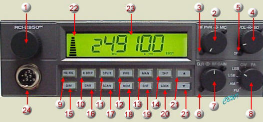 |
- FREQUENCY SELECTOR
This control is used to select a desired
transmit and receive frequency.
- RF POWER CONTROL
This control allows the user to adjust RF
power output.
- MIC GAIN CONTROL
Adjusts the microphone gain in the transmit
and PA modes. This controls the gain to the extent
that full talk power is available several inches
away from the microphone. In the Public Address
(PA) mode, the control functions as the volume
control.
- ON/OFF VOLUME CONTROL
This knob controls the volume and the power to the
radio. To turn the radio on, rotate knob
clockwise. Turning the knob further will increase
the volume of the receiver.
- SQUELCH CONTROL
This switch is used to eliminate background
noise being heard through the receiver which can
be disturbing when no transmissions are being
received. To use this feature, turn the control
fully counterclockwise and then turn clockwise
slowly until the background noise is just
eliminate. Further clockwise rotation will
increase the threshold level, which a signal must
overcome in order to be heard. Only very strong
signals will be heard at a maximum clockwise
setting.
- RF GAIN CONTROL
This control is used to reduce the gain of the RF
receiver amplifier under strong signal conditions.
- CLARIFIER CONTROL
Allows tuning of the receive frequency above or
below the assigned frequency by up to 500 Hz.
Although this control is intended primarily to
tune in SSB/CW signals, it may be used to optimize
AM/FM signals.
- MODE (FM/AM/USB/LSB/CW/PA) SWITCH
This switch allows you to select one of the
following operating modes: FM/AM/USB/LSB/CW/PA.
- NB/ANL BUTTON (NB/ANL)
In the NB/ANL position, the RF Noise Blanker and
Automatic Noise Limiter in the audio circuits are
also activated. The Noise Blanker is very
effective in eliminating repetitive impulse noise
such as ignition interference.
- ROGER BEEP BUTTON (R.BEEP)
In the Roger Beep position, the radio transmits an
audio tone at the end of your transmission to
indicate that transmission has ended. As a
courtesy to others, use the Roger Beep only when
necessary.
- SPLIT BUTTON (SPLIT)
This control activates the offset frequency
function. It causes the transmit frequency to be
offset either above or below the receive frequency
by a user programmable amount to allow operation
of an FM Repeater.
- PROGRAM BUTTON (PRG)
This button is used to program operating or
scanning frequencies into memory. See the
OPERATION section of the manual for further
details.
- MANUAL BUTTON (MAN)
This is used to return the unit to manual mode.
- SHIFT BUTTON (SHF)
This is used to select 100 Hz, 1 KHz, 1O KHz, 100
KHz or 1 MHz frequency steps.
- DIM BUTTON (DIM)
This button adjusts the display backlighting in
four different steps to best match the ambient
light.
- SWR BUTTON (SWR)
This control is used to check SWR.
- SCAN BUTTON (SCAN)
This is used to scan frequencies in each band
segment. The OPERATION segment of the user manual
provides detailed information on using the SCAN
control.
- MEMORY BUTTON (MEM)
This button is used to program memory channels.
Detailed information on how to use this control is
provided in the OPERATION section of the user
manual.
- ENTER BUTTON (ENT)
This is used to program frequencies in memory. See
the OPERATION section of this manual for more
information on using this control.
- LOCK BUTTON (LOCK)
This button is used to lock a selected frequency.
Press it to activate the switch. In this position,
it disables the Frequency Selector Control,
up/down buttons on the front control panel and
remote up/down buttons on the microphone.
Repressing the switch will unlock the frequency.
- UP/DOWN SELECTOR
These buttons are used in conjunction with the
shift key to move the frequency upward or downward
to select a desired frequency.
- METER
This meter indicates received signal strength,
transmitter RF output power and SWR level.
- LCD DISPLAY
The LCD displays the frequency selected, functions
and memory channel.
- MIC JACK
Accepts 6 pin female connector with a type
Philmore T616C or Calrad 30445 style connector.
|
Programming
-
Memory Channels
Press PRG, then press MEM, then enter frequency,
then press ENT. To select any of the 0-9 memories,
press MEM each time to step to the next desired
memory channel.
-
Scan Range
Press PRG, then press SCAN (SCAN+ will appear on the
display), then enter frequency for the high scan
limit, then press ENT, then press SCAN (SCAN- will
appear on the display), then enter the frequency for
the low scan limit, then press ENT.
Unlike the 2950, setting the
scan limit doesn't limit the frequency operation
outside the scan mode, even though the DX user
manual states it will.
-
Frequency Split
Press PRG, then press SPLIT, enter the desired
frequency split, then press ENT.
|
Memory channels are accessed by
pressing the MEM button. Each time the MEM button is
pressed, the memory advances one channel. To exit the
memory channels, press the MAN button.
Two scan options are available,
memory scan and frequency scan. Frequency scan will scan
between the high and low limits programmed. If no limits
are programmed, the radio will scan the entire frequency
range of the radio. Squelching the radio starts the radio
scanning. Once a signal breaks through the squelch, the
radio pauses until the signal no longer breaks the squelch
for about a second. Pressing the SCAN button once
indicates a SCAN(+) on the display and causes the radio to
scan up. Pressing the SCAN button again indicates SCAN(-)
on the display and causes the radio to scan down.
The split frequency is selected by
pressing the SPLIT button. Pressing the SPLIT button once
indicates SPLIT(+) on the display and causes the amount of
frequency split programmed to be added to the receiver
frequency during transmission. Pressing the SPLIT button
again indicates SPLIT(-) on the display and causes the
amount of frequency split programmed to be subtracted from
the receiver frequency. Pressing the SPLIT button a third
time shuts off the split feature.
If you've never used a 2950 before,
it comes with a user manual that Wayne from QST correctly
regards as adequate that will help you master the
functions. If you liked the 2950, you�ll love the 2950DX.
This is a great dual band radio for the money; I recommend
it for anyone that takes radio seriously. If you weren�t
impressed with the old 2950, like myself, I think you�ll
have a different outlook on Ranger Communications Inc.
after trying one of these!
Bob F
One detraction of the RCI 2950 is the digital Bar S Meter!
This can be effectively overcome by adding
a external connection to an Analogue Meter.
There is an empty block on the board to the right of VR2
called J16. The block has 5 solder dots, the end one (the
one named MT) carries the positive dc voltage for an
external signal meter. Turn on the rig with the case off
and find which terminal on J16 with a multimeter. The
terminal gives between 100 and 1000mv depending on the
signal strength which is enough to drive an analog meter.
The ground can come from any good ground on the board.
Beats the hell out of the digital onboard meter using a
half decent analog external meter. When you turn on the
external meter, the dc current drain shuts down the
internal digital meter and drives the external one quite
nicely. |